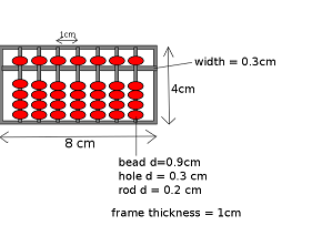
I had a small plastic abacus when I was a kid and it was torn apart because I needed to practice beading for a competition (what a weird competition!); so I decided to 3D print an abacus for this week's project. I looked up some images of an abacus online and came up with the rough measurements for my abacus. I made a quick initial sketch in Inkscape.
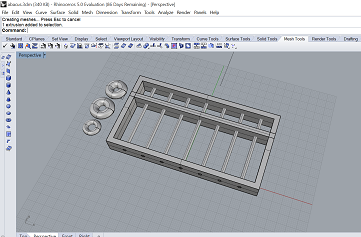
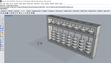
I then tried to learn how to create my design in Rhino. It was a steep learning curve and I didn't find it very intuitive. I learned a bit more on how to use the software from Nathan (one of the Teaching Fellows) and was able to get the frame and the columns:
I used the Torus shape in Rhino for the beads; but I had trouble figuring out how to get the torus into the right size and shape. So I asked Oliver, another Teaching Fellow, for help. And he helped me a lot!! Here's his explanation on how the 2 radii interact in a torus:
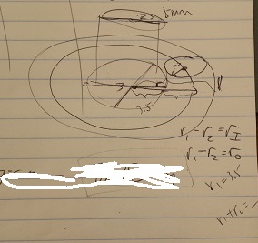
He suggested that I made the abacus bigger because otherwise it might be too tiny. He also suggested printing the abacus standing up rather than lying down, because if it were lying down, there would have to be support structure inside the beads to hold them in relative position with the column; and as a result, it might be hard to separate the beads from the column. If it were printed standing up, I would only have to pull the beads up to separate them. We scaled the abacus such that the length would be 15 cm. He also helped me create multiple copies of the bead and place them around the columns, making sure that they are lined up in the same plane as the abacus. Then we made stacks of beads which are 1 mm away from each other. Here are a picture of the final design and the file of the abacus:
We loaded it into Cura15.02.1 to adjust the print settings and get the time estimate for the printing. It seemed that the abacus would need more than 6 hours to print; so we decided to scale it down by half in all three dimensions. The small abacus is 1/8 as big as the original one.
I used both used Ultimaker2 and LulzBot to print the abacus. Here are the settings I used:
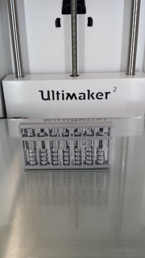
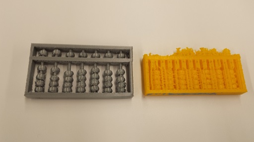
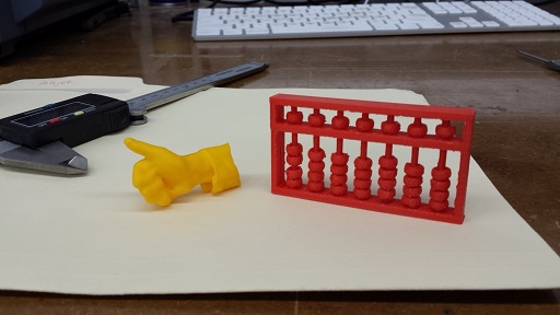
I used the same settings for both machines. I did not remove the support structure for the one from LulzBot because it looked too messy. The one from Ultimaker 2 had a better texture and the support structure was very easy to come off. The beads could move up and down freely after I pulled them apart. However, the entire abacus looked very fragile. The outer layer of the top horizontal frame looked like it was about to come off and one of the the columns broke as I was trying to separate the beads. So I had to use super glue to glue it back.
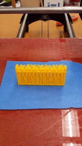
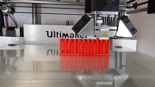
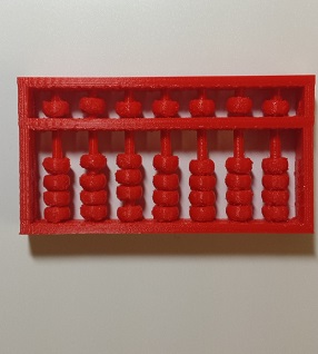
Over the weekend I printed another (and supposedly better) version. I used the red filament this time; and Daniel, a student from the Harvard Section, said that the red filament requires higher temperatures than the grey metalic filament, even though they are both PLA filaments. So I used the custom settings he created for the red filament. I have noticed that if the nozzle and the buildplate were not hot enough the red filament would not come out of the nozzle and stick to the buildplate properly.
I used the following settings to print out the red abacus:
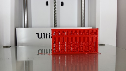
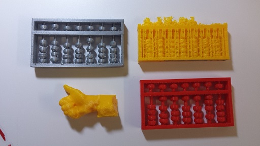
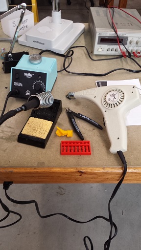
The red abacus was very robust-looking; but the support structure was much firmer as well and harder to take out. I spent 2 hours taking out the unwanted parts with a cutting tool. Per Daniel's suggestion, I also used the soldering iron and the hot air gun to smoothen some of the rough surfaces on the beads and columns. It still looks pretty rough and the beads don't really move smoothly along the columns. It looks like there's a trade-off between the quality of printing and the ease of removing support structures.
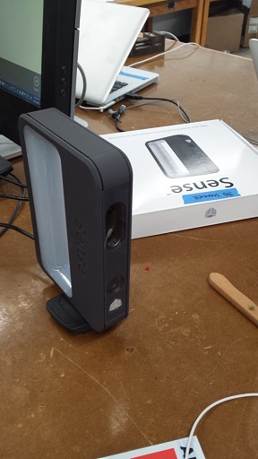
3D scanning turned out to be not as easy as it seemed. I tried to scan both a person (myself) and a small object (my hand). Here is the Sense scanner that we used:
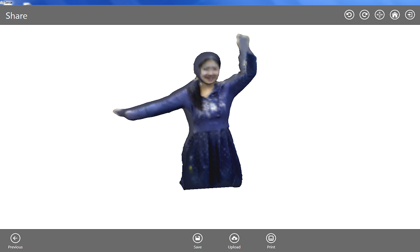
I first tried to do a full-body scanning of myself by placing the scanner on the table and turning around at a fixed spot. For some reason the scanner lost tracking very easily, especially when I turned my back against it. I was able to get a (almost) full image after several trials and errors. The cool thing about the Sense software is that we can rotate the image (by right-clicking) and erase the unwanted parts that happen to be captured. The "solidify" function helps fill in any gaps or missing parts. We can also do some simple trimming on the object.
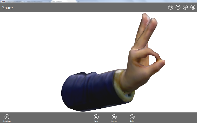
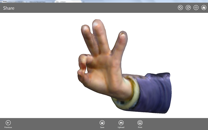
Then I tried to scan my hand using the "Small Object" option. I've found this option easier to use because it only tries to capture things in the circle and it's easier to recover from lost tracking. I scanned an "Okay" gesture as well as a thumbs-up:
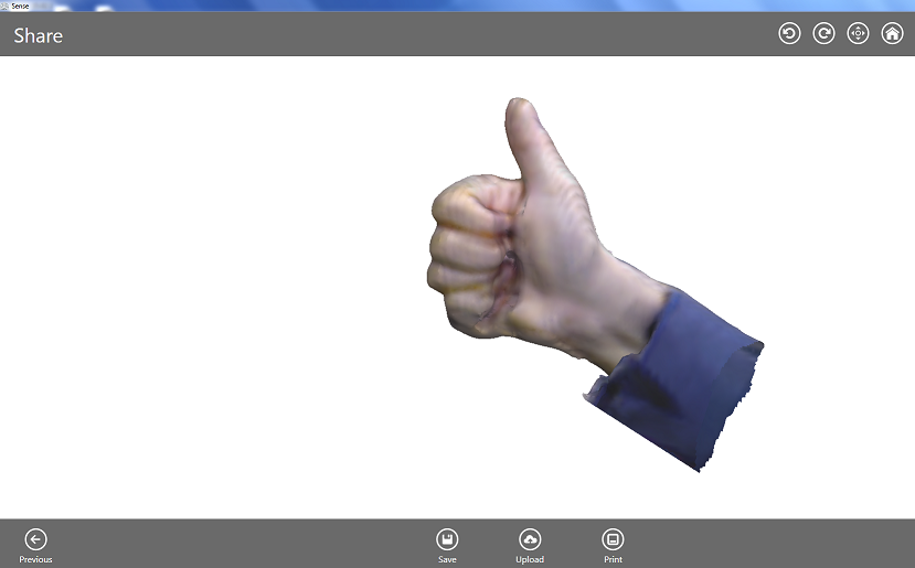
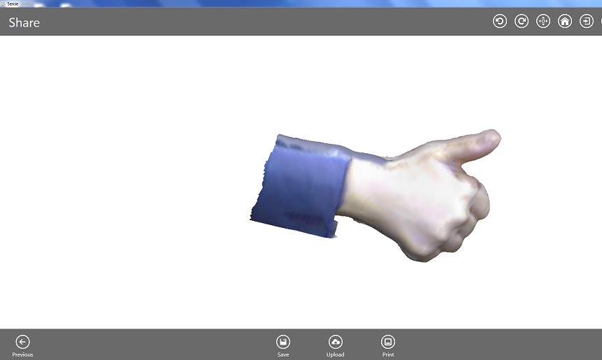
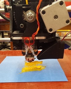
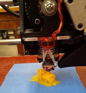
I tried to print the thumbs-up, but it would not print properly. The middle portion of the hand was missing:
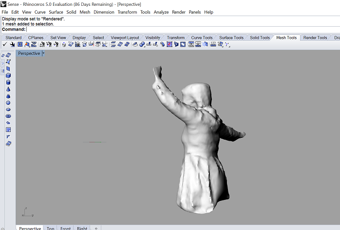
Then I imported the .stl file into Rhino and realized that it was actually an open mesh. In order for it to print properly it has to be a closed mesh. Oliver gave me some instructions on how to close an open mesh in Rhino:
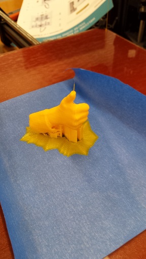
The original open mesh had hundreds of naked edges; and I had to follow the above steps a couple of times. I also used the "Reduce Polygons" and "Mesh Boolean Tools - Union" functions that I found through some online searching, and I was not quite sure whether they helped. I am still not sure how it worked, but I managed to get a closed mesh in the end! The printing worked well this time. I scaled my original object by a factor of 0.25 in all three dimensions. I used roughly the same settings as the ones for printing the abacus and it took about 50 mins to print. Here are the .3dm file (Rhino's default format) and the .stl file of the thumbsup. What is strange though is that the .3dm file is able to save the closed mesh, but the .stl format ends up as an open mesh again when I re-opened it in Rhino. Before printing the thumbsup using the .stl file, please be sure to use the "MeshRepair" function in Rhino to turn it into a closed mesh.
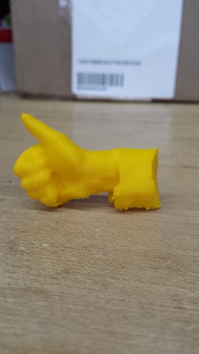
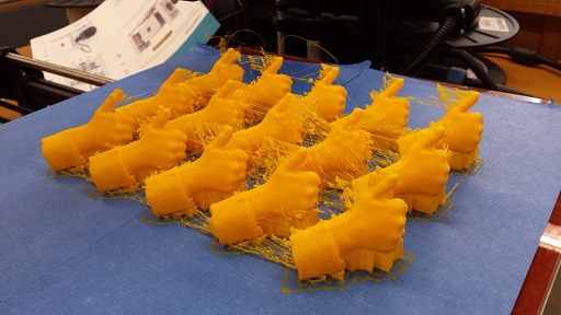
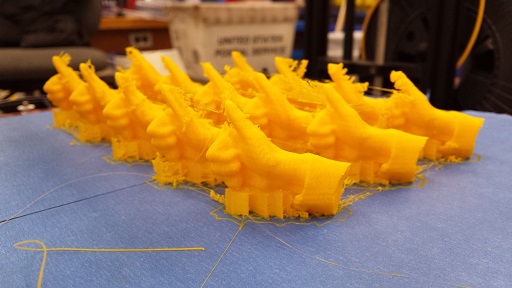
It looks so cute and it can actually stand on its own! Daniel and Dixon were with me and we thought that it would be cool to throw thumbs-up at people when we like their ideas or want to encourage/support them in some way; so we "cooked" a batch of 15 and I left them for the other people at our section to take. I think that it would also be cool for teachers to give students thumbs-ups to motivate them to learn.
I spent a lot of time in the lab this weekend and it was so much fun!